Capstone II: Progress Blog #1
- John Santos
- Sep 9, 2020
- 3 min read
Updated: Sep 11, 2020
From the beginning of the fall semester in late August, the team has begun to order the components as listed in the Bill of Materials in prior blogs. As the items begin to arrive, team members have started assembling the skeleton as part of our prototype, using the Solidworks model as a guide. The base floor of the device was decided to be cut from pegboard, which is light, thin, and easy to screw into due to the premade holes. The walls housing the compression system were made from 1x2 wood that was sturdier. Based on the Solidworks model, the walls and base were cut using a miter saw. A grinding wheel and file was used to smooth out any sharp edges. Circular cuts, as per our Solidworks model, were cut to allow the BVM to rest on without falling out (Figure 1).
Aside from our prototype, we have also started building the circuit diagram consisting of the Arduino Uno board, servo motor, OLED screen display, rocker switch, stop button, resistors and rotary encoders (Figure 4). Currently, it is nearly finished as it needs revision from someone within the electrical component expertise to confirm there will be no issues with the connections or risk of shorting the circuit or causing any explosions. Resistors have also been implemented into our circuit, but determining the correct value is yet to be found.
When cutting the semicircular cuts in the walls for the curve of the BVM to rest, the first set of walls were too short to allow the BVM to rest without interfering with the DC motor and pinion below. This was remedied by cutting another pair of walls more precisely, giving at least 6 cm of clearance for the DC motor to operate, since the DC motor itself with the pinion was 5 cm tall (Figure 2).
At first, we anticipated to make the rack holders by gluing pieces of thin wood together to form a slot, but getting a tight fit given the small width of the rack proved unfeasible. Therefore, the team will opt instead to 3D print the rack holders.
Previously in the Spring 2020 semester, research on individual components of the circuit diagram was completed. Putting together all the components in one single diagram was not an issue since our research had already provided the details of which pins to use from the Arduino Uno board for a specific component. However, the team recently found that some of these components needed resistors in order to prevent excessive current coming into the part. Determining how much resistance to use on components such as the rocker switch and push button need to be found. Our solution to finding the correct value of this resistance will be found by using the part specification ratings in the datasheet. This includes the voltage and current passing through the circuit, and then using Ohm's Law to find the required resistance.
As more and more of our components arrive, we plan to send requests for the 3D Print Lab at UH to print our Clamps and Rack holders. Once all components are gathered, we plan to meet physically to assemble the device. Also, to measure the output tidal volume, a correctly functioning spirometer will either need to be borrowed, or a volumetric measuring device will need to be devised and set up in the near future for testing. Ideally, a functioning prototype will be completed by mid-October.
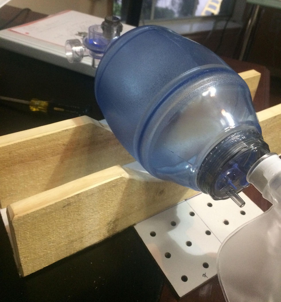
Figure 1: Initial Build of the Framework of the Device
The height of the walls is also determined based on the height of the servo motor underneath the bag. While the device is running, the clearance as shown below would prevent the bag from interfering with the motor and electrical components.

Figure 2: Revised Set of Walls with at least 6 cm clearance for DC Motor and Pinion
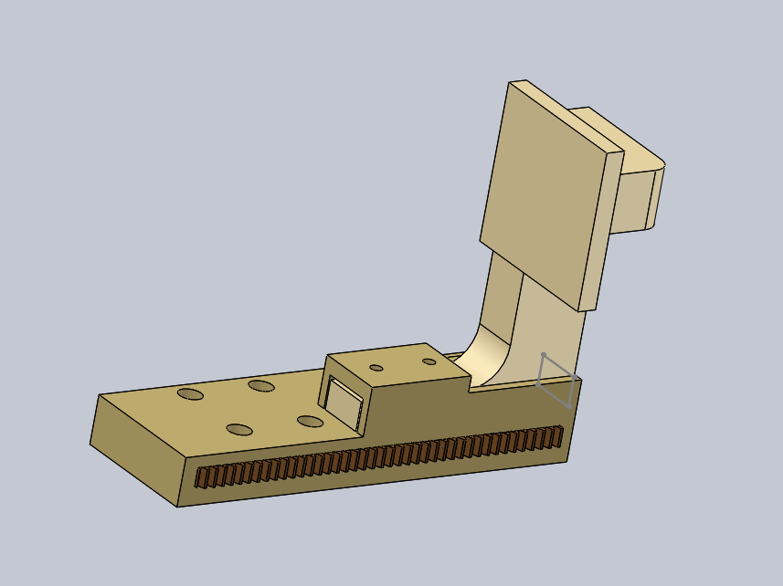
Finally, the team has revised the clamps to provide better stability. Previously, the leg was extended outward (on the opposite side of the hammer), which likely would cause a larger bending moment due to the resistant force of the bag after each compression. Also, a longer leg would create a longer rack holder, which would result in using more material and an additional sliding carriage. Creating a leg going inward (on the same side as the hammer) would decrease the bending moment while maintaining the current length of the rack holder underneath the leg.
(Hammer is the square surface that will be in contact with the bag during compression)

Figure 3: Modified Clamp with pivot
The arduino circuit diagram once revised, will serve as an amazing visualization that will guide the team once the circuit is built. Time will be saved when this portion of the project has begun, as all the connections will be known leading the jumper wires to certain pins of the Arduino Uno board. This diagram will also be part of our deliverables, helping those who try to replicate the design.
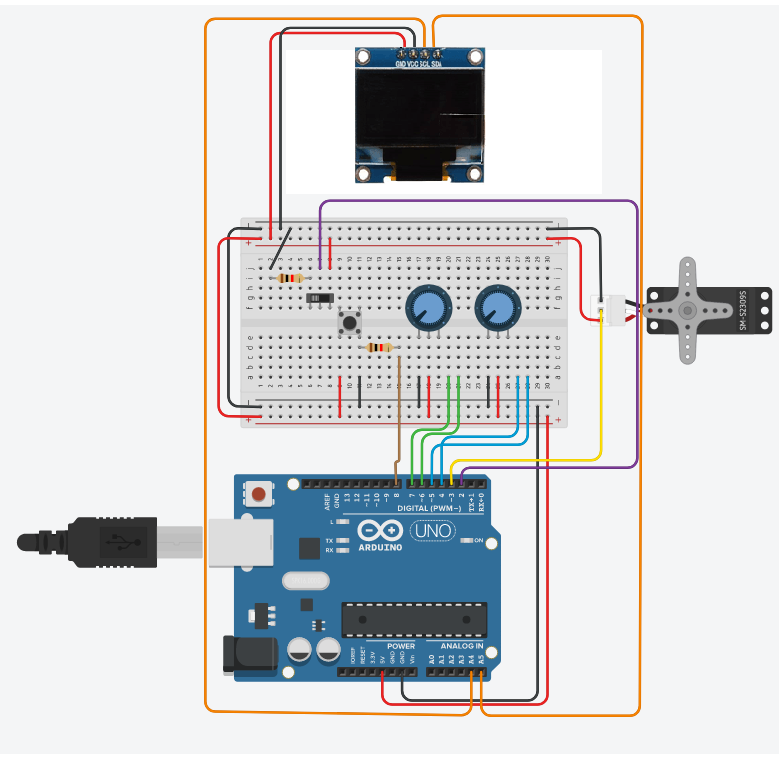
Figure 4: Arduino Circuit Diagram with all necessary components


Comments