Capstone II: Progress Blog #3
- Kyle Le
- Oct 23, 2020
- 4 min read

Our progress for the time period of time October 7 to October 23, Team 7 has finally finished the main housing of the prototype. The device, as planned before in the Spring semester, is based around a servo motor and pinion in the middle of the device. The brass pinion gear is connected to two plastic gear racks, which are embedded in 3D printed rack holders. The rack holders are screwed on top of a pair of purchased linear guide rails so that they can slide horizontally. On top of the rack holders are the 3D printed clamps. When the pinion rotates counterclockwise, the clamps both move inward, squeezing the bag, and when it rotates clockwise, the clamps move out for an exhalation. The team so far has made an Arduino code that can control the OLED screen for setting the TV, I:E Ratio, and a Run/Idle State by using the knob/button. Also within the code is a way to put the servo motor in a rotation loop when the user selects the “Run” option.
To calibrate the Tidal Volume output, initially during Spring, the team searched for a Wright Spirometer, which directly tells the output volume, but those found were too expensive. The team reached out to a Thermal Fluids professor to gain insight about this, and learned about two possible alternatives: the peak flow meter and an anemometer. The peak flow meter was first investigated: it outputs a volumetric flow rate in Liters per minute, which the team could theoretically multiply by the inhalation time to get a total volume. But when the team did order one, it was not sensitive enough to respond to the lower air pressure of the BVM, so it was returned. The second alternative that was chosen was the use of a fan anemometer shown in Figure 1 to measure output wind speed.
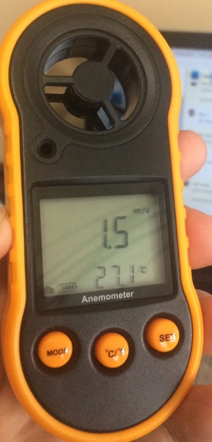
Figure 1: Fan Anemometer, which will be key in calibrating Tidal Volume
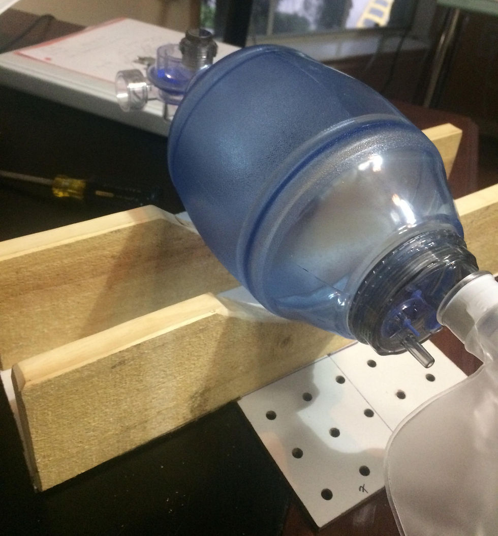
The calibration of the TV and I/E ratio has begun and is almost complete. The anemometer we purchased was sensitive enough to pick up the slower output wind speeds of the BVM, but has a low resolution of 0.1 m/s. The anemometer was placed parallel to the expiratory valve to record the speed of the air coming out of the bag under compression by the clamps, as seen in Figure 2. The speed was multiplied by BVM output area to get a volumetric flow rate. From then, we’ll multiply that volumetric flow rate by the set inhalation time to get an estimate for total delivered tidal volume. The inhalation time was found by starting a timer when the clamps made contact with the BVM and then stopped until the clamps reached the initial starting point. The team anticipates to have some uncertainty for the speed given by the anemometer and some error in the placement of the device, as different speeds will yield based on where the output of the air that contacts the fans.The inhalation time will also have some slight error, as the timer is started and stopped manually.

Figure 2: Anemometer placement parallel to expiratory valve
One major issue we faced during the development of the code was the initial rotation direction of the servo motor. Based on the positioning of the clamp and rack system, the servo motor has to rotate counter-clockwise within the plastic racks to allow compression of the clamps. The code was altered so that the rotation angle of the servo motor is set to its max, causing the pinion to have already rotated clockwise, and then be able to rotate counter-clockwise once the operation begins.
Secondly, the team has encountered problems in regards to the sensitivity of the rotary encoder when dialing in the TV and I/E outputs on the OLED display. Although the code is set with adjustable tidal volume increments of 100ml and I/E increments of 1 second, oftentimes the adjustments can either skip the nearest level, or will fail to adjust when needed. Additionally, after several trials in the attempts to alter the code to reflect accurate output readings, the team had noticed that the current rotary encoder has become unresponsive and is currently not in working order. However, the team has spare parts that will quickly resolve this issue.
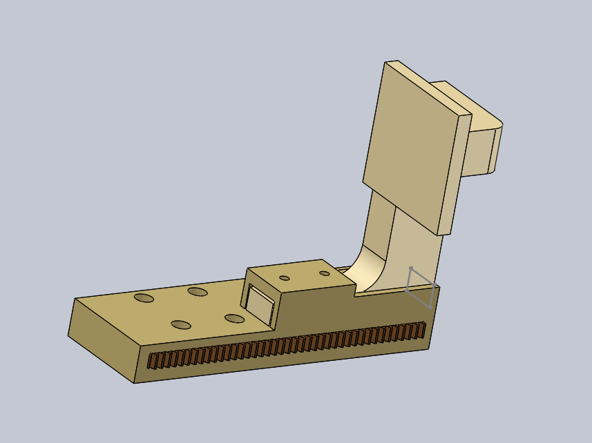
We also had another issue with the second iteration of clamps not fitting correctly onto the rack holders and thus not aligning properly as to meet the exact center of the BVM. The team resolved this issue by editing the main Solidworks Assembly based on precise measurements of the physical prototype, as shown in Figure 3.

Figure 3. Final Isometric Model of the Prototype with taller Holding Walls and final Clamp Design.
The final housing for the prototype features a pegboard base and holding walls made of wood. This redesigned housing provides better clearance, preventing the bottom of the BVM to have direct contact with the servo motor underneath.The clamps were redesigned for one final time based on these exact physical measurements, rather than having to guess and check repeatedly. Below in Figure 4 is our latest and hopefully final clamp design iteration, this time featuring a taller “neck” and a curved face for better contact with the plastic of the BVM.

Figure 4: The Final Design Iteration of 3D Printed Clamp
The final clamps frame were extended because of the raised walls in the final housing of the prototype, allowing alignment with the center of the BVM.
From October 23rd to November 6th, the team plans to finalize the code, then finish the calibration/validation process for the Tidal Volume output and I:E Ratios. For the calibration mentioned earlier, we had to manually input the motor speed and angle rotation. Once the calibration is finished, then the code will now have multiple conditional statements where the settings displayed in the OLED screen will now match the outputs of TV and I/E ratio from the bag. We expect the input rotation angle to not exactly match that of the actual pinion gear, and so we need to calibrate our inputs based on that.
We also plan to finalize the housing of the circuit and wiring within the main body of the prototype, but being a relatively minor task, this will come after the TV and I:E Ratios are fully calibrated and fully integrated into the Arduino code. The material used for the housing of the circuit will likely be made of wood similarly to the housing of the whole device with a possibility of plexiglass as an alternative.

Comments