Capstone II: Progress Blog #2
- John Santos
- Sep 22, 2020
- 4 min read
Updated: Sep 25, 2020
Current Progress
In summary, Team 7 has obtained most of the necessary components needed to assemble the first iteration of the device. As of this blog being published, the team is only lacking some of the basic hardware to create the frame for the BVM. The first iteration of the clamps and rack holders, as in Figure 1, have been retrieved from the 3D printing lab at UH. However, they are in need of a redesign as the team has a new plan to have the moving components attached to the more stable base instead of the walls (Figure 2).
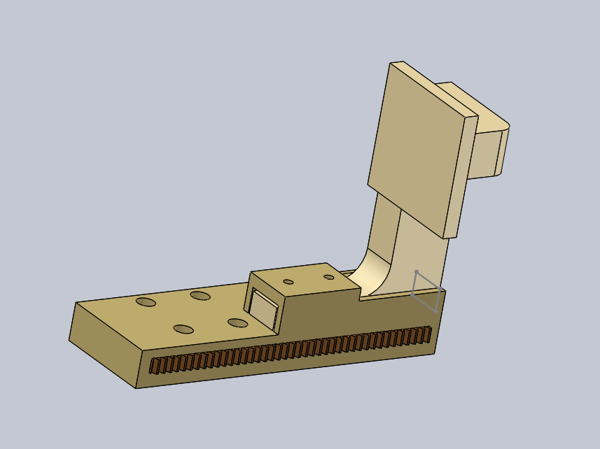
Figure 1: Initial Clamp and Rack holder System designed and obtained from the UH 3D Printing Lab

Figure 2: Our idealized fit between the walls where the rack holders mate perfectly with the pinion and the clamps meet perfectly together when pressed.
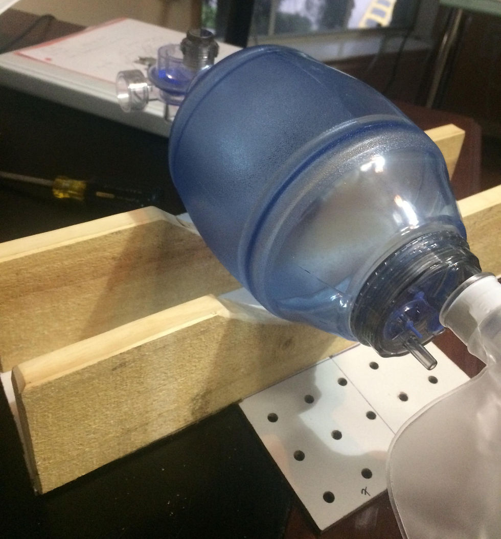
In this new configurement, the walls will only be there to guide the moving carriage blocks and support the BVM. In addition to the acquired parts and the redesigned clamps/holders, the team has also researched and begun the Arduino code that will control the servo motor. The current code consists of closed loop functions that will alter the speed and frequency of the motor, however it does not yet correlate these functions with a command given from the LCD screen/dials. The team also created a schematic of the electronic assembly to gain an understanding how these components will interact with one another and function when it comes time to integrate the system into the mechanical portion of the project. As a side note, a thin piece of wood was screwed across the walls as a safeguard to prevent the bag from expanding downwards into the pinion when compressed.
The circuit diagram representing our hardware was completed. Establishing the placement of our hardware will help the team produce the electrical schematic diagram as part of our deliverables. There will be symbols and configurations that will be unknown once we begin the diagram. Reading through a variety of schematic examples will allow us to complete this portion of the project.
Design Issues and Solutions
Despite the pouring rain, one of our team members braved the storm to pick up the 3D printed parts on Monday the 21st. The 3D printed parts ordered seemed good at first, but there were several tolerancing problems, mainly on the rack holder. The first and most obvious issue was that the slot in the rack holder in which the “leg” of the clamp was to be inserted was 3D printed in instead of being hollow, likely due to the 3D printing process, as shown below in Figure 3. The first remedy used overcome this minor problem was to drill progressively larger holes where the slot was filled, then use a flat-faced file to smooth out the edges to the final slot form, but we would later find out that there were a couple more issues.

Figure 3. The reality of how the 3D parts fit within our base. The slots where the rack was to fit in the holder were too small, the clamps were too stubby, and there was little space for the DC motor and pinion, prompting a redesign.
The slot in the side of the rack holder in which the rack was to go was not wide enough for the rack to fit. Thirdly, when performing a loose fit of the 3D parts onto the base assembly, there was no room in the middle of the base between the walls for the pinion/motor to be placed. This could be fixed by simply moving the two walls further apart, but doing so would necessitate a lengthening of the clamps to ensure they would meet in the middle of the BVM.
We seek to remedy this problem mainly by redesigning the rack holders in such a way as to:
Widen the rack holder slot
Modify the attachment of the holder to the clamp in a way that has no hollow spaces
Be narrowed as to allow sufficient space for the pinion/motor to fit properly in the center
As the holders are redesigned, the clamp arms will need to be lengthened and adjusted accordingly as to align at the center of the BVM and to account for the carriage blocks and rails.
Plans for the Future
A redesign of the clamps and rack holders will be in order for the 3D print lab and will come sometime during this period of time. Once the 3D printed parts are finished, we expect to begin assembling the mechanical compression system as soon as possible. The frame that had initially been started with the pegboard and the 1x2 pieces of wood will be improved as needed for initial design flaws. Usage of a different wooden medium other than pegboard as the base is being discussed.
The redesigned rack holder that was sent to the 3D print lab has a wider slot for the rack. The new rack holder will exclude the "ceiling" support that was previously unable to be fabricated by the lab. The team has decided to widen the walls to make more room for the motor and two rack holders. As a result, the arm of the clamps will need to be extended to ensure the clamps will align with the center of the BVM. The team is currently working on the modified clamps and will send them to the 3D print lab as soon as possible.
While waiting on the 3D printed parts, development of the Arduino code will continue. Currently, the servo motor is being tested to control the I/E ratio through time delay while the Tidal Volume output will be followed through controlling the maximum angle at which the motor will spin. We expect to have trouble configuring and calibrating the code for measurements of our outputs since there will be plenty of testing through variable changes.


Comments