Capstone I: Progress Blog #4
- Kyle Le
- Apr 17, 2020
- 5 min read

Updated: Sep 9, 2020
The progress the team has made from March 5th - April 17th:
Over the work period of March 5th - April 17th, the team had conducted a complete research analysis of medical constraints and standards in order to adhere to the requirements of mechanical ventilators established by the International Organization for Standardization (ISO), International Electrotechnical Commission (IEC), and The U.S. Food & Drug Administration (FDA). The team has reviewed the standards associated with the construction of our medical device and has also identified essential parameters that dictate the performance of the ventilator.
In order to execute the mechanical compression of the BVM in reference to the identified medical parameters, the team continued by sketching two conceptual designs of the BVM attachment. The following designs consisted of similar rudimentary components such as the use of a DC motor, voltage source, microcontroller (arduino), rack and pinion, and clamping mechanisms. However, each of the designs varied in the orientation of the device in reference to the user and patient.
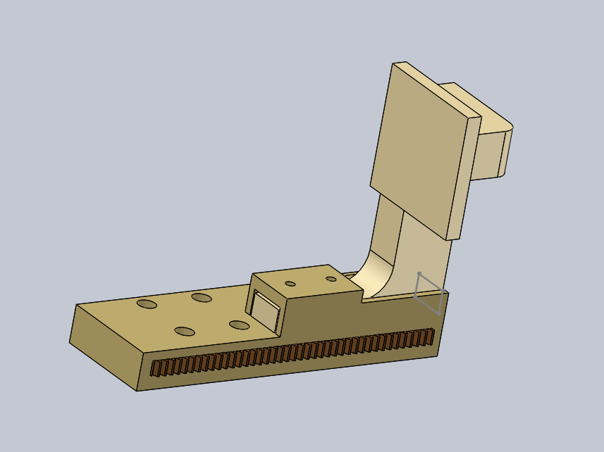
To further our understanding of the various issues of the BVM and our mechanical attachment, the team proceeded by purchasing the Lightning X MPR Bag. This allowed the team to understand the amount of force the bag requires for each compression, in addition to the amount of displacement the bag experiences during the compressions. Furthermore, we were able to measure the dimensions of the BVM and create a 3D model for size comparisons, component selections, and concept alterations.
Throughout the duration of our current work period, team 7 has continued to reach out to healthcare professionals in order to reference the needs of our device and further our understanding of the requirements needed in various clinical scenarios. Over the course of our extended spring break, the team had reached out to the University of Texas Medical Branch at Galveston who had been working on a similar medical device during the COVID-19 outbreak. Through the collaboration of medical professionals, engineers, and other participating universities, the team was able to narrow down the selection of electronic components to mediate the performance of the DC motor, evaluate quantifiable data for tidal volume and PEEP, and consider improvements to our design options.
To expedite the selection of our current designs options for the mechanical compression attachment, a design analysis matrix was created in order to narrow down the pros and cons of each concept. This helped us differentiate between the two designs as we advanced to the next stage of creating CAD drawings. During the week of April 12th-18th, the team completed CAD drawings via Solidworks of the two conceptual designs mentioned previously. Both drawings are similar in nature and use roughly the same components, but differ in the orientation of the mechanical clamping mechanisms.
Because the longevity of the device is a key benefactor in the operation of our device in a medical setting, a FEA analysis is currently under-way so that the regions of high stress concentrations can be identified. So far, the team predicts that the meshing of the rack and pinion will be the primary area of stress as the continuous changing of motion along the horizontal axis will provide for the wearing of the gear teeth. Furthermore, the team also predicts the areas where the clamping mechanisms join the rack will provide for an additional stress concentration region that will be accounted for during the material selection/construction phase of the device.
The proper selection of a DC motor and the selection of a clamping mechanism will dictate the performance of the compression attachment, and currently the team is providing detailed calculations of motor specifications and tidal volume outputs relating to BVM compression. In order to minimize costs, the angular velocity and torque specifications of the DC motor will be chosen based on the selection of an attached gear to the shaft. The RPM of the motor and gearing system will affect the rate at which rack compresses the BVM, while the torque affects the amount of force along the horizontal axis. Furthermore, the team is estimating how the surface area of the clamping mechanism will output a given tidal volume per distance displaced along the horizontal axis as well.
As the calculations, CAD drawings, and FEA are completed, an updated bill of materials and budget will also be included to account for extra material needed. Research on electric components of the design has been done which consisted of the servo motor, LCD screen, knobs, and On/Off switches. We have a better understanding of how to maneuver the code, which pins to use on the Arduino UNO board, and which other small components will be needed such as resistors, jumper cables, and pin headers.
Progress on CAD and FEA:
Design #1: Below is a two-sided compression rack/pinion design with right-angled arms. It is deemed unable to handle most stress due to the concentration of forces at the corners, which can be seen in the FEA analysis in the next section.

Design #2: Two-sided compression rack/pinion design with more streamlined angled arms. This option is slightly better than the right-angled arms at having less concentrated stress at corners but still has significant bending moments.

Below is an FEA analysis of the 2 mechanisms, showing structural effects in terms of displacement, strain, stress, respectively, when the clamp is being pressed by the bag. The first three figures below here are for the streamlined angled arms:


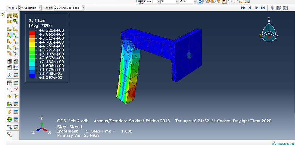
Below is the FEA analysis for the right-angled arm, which was previously shown in the Solidworks models.


These analyses will help us determine the appropriate materials and modify the dimensions of key components accordingly.
Torque and Power Calculations:
The team also performs preliminary calculations to determine the required force applied on the bag by the clamps, torque, and power of the motors. The team uses two different methods; one does not take into account the mechanism and one considers physical measurements of the mechanism.

The required torque for the motor should be larger than 1.1 Nm or 11.2 kg-cm. This will help determine which motor should be used for the design.
Current challenges and proposed solutions:
Throughout the following work period, the team has experienced delays occurring primarily during Milestone 3 (FEA analysis, CAD drawing, and motion simulation), and minimal delays during Milestone 2 (Circuit diagram & calculations). The delays can be attributed to the mandatory quarantine due to the COVID-19 pandemic. The outbreak of this viral disease has caused the University of Houston to temporarily shut down for an extended length of time and forcing members of Team 7 to remain sheltered at their houses as well. Because of these factors, several campus resources such as engineering software, library databases, and personal consulting have been unavailable. Furthermore, the team has been temporarily affected by the difficulties in coordinating our work schedules and online meetings. The transition of classes from in-person lectures to an online format has posed certain delays as the team is adjusting to a new work-load as full-time engineering students.
To solve the delay in our itinerary mentioned previously, we rescheduled the tasks involving the sourcing of supplies and gathering research of our circuits, electronics, and coding from April to the summer months. This would streamline the workload for the remainder of the Spring semester and would allow the team to focus on the mechanical engineering portion of the project. Our relative inexperience in electrical engineering can be more easily alleviated during the summer when there is more time to conduct research. Furthermore, the team has continued to deliver the items listed in Milestone 3 by the end of April and is working diligently on the remaining design aspects of the mechanical compression attachment.


Comments